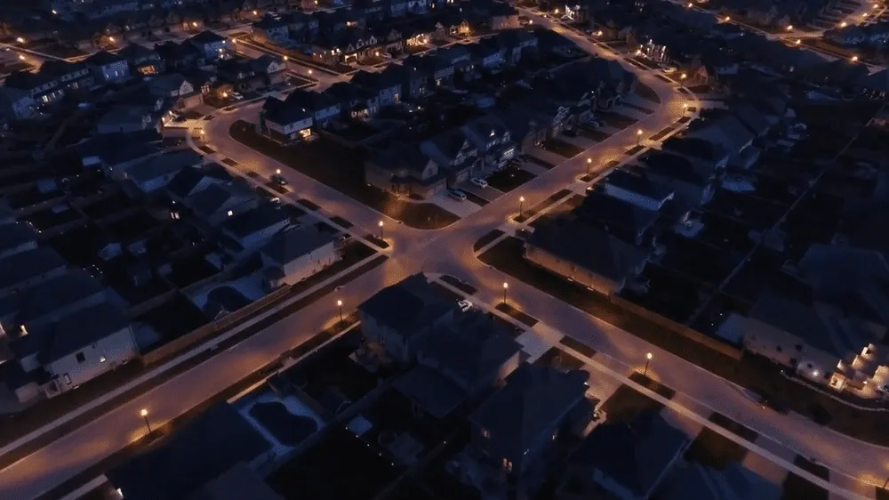
Lighting Simulation for Solar Street Light Projects
Lighting Simulation for Solar Street Light Projects

Short answer: simulate the light, then feed the result straight into the energy calculation — on a solar project the two are one problem. The lighting model tells you how many watts the road needs; the energy model turns that wattage into a panel and battery. Run only the first half and you get a beautiful report attached to a fixture that dies by February.
The DIALux workflow, and what each step decides
DIALux is the standard road-lighting calculation software; it takes the fixture's photometry (its IES file) and computes illuminance on a modeled road. The workflow:
- Draw the area. Import the site layout — parking lot, urban road, campus path — and set the terrain, including obstacles that will block or reflect light.
- Add the fixtures. Select the model and place it: mounting height, pole spacing, and aim. Spacing and height do more for uniformity than any other parameter.
- Configure the parameters. Set the flux, distribution type, and operating mode. For solar fixtures, model the dimming profile here — the night is not one constant output.
- Run the simulation. Generate the illuminance maps and uniformity reports. Check for dark spots between poles and for glare hot spots near windows or driveways.
- Export the report. The maps and tables become the deliveriable your client and the road authority review.
The step most projects skip: feeding the energy side
This is where a solar project diverges from a grid project. The simulation output — required wattage and nightly runtime — is the input to the energy calculation:
- Consumption. Nightly watt-hours come from the lighting result, not from a guess.
- Panel sizing. Match the panel to local climate: peak sun hours and worst-month irradiance set the array, not the annual average.
- Battery sizing. Size storage for the cloudy-day autonomy the project demands — typically several days of reserve, which is what keeps the road lit through a gray week.
- Oversizing control. An accurate lighting calculation is what stops the battery from being oversized to cover a fat photometric design. Every watt trimmed at the fixture is a watt the battery does not carry.
Done together, the two calculations converge: a tighter distribution lets you drop fixture wattage, which shrinks the battery, which shrinks the panel. Done apart, each side pads its own margin and the client pays for both.
Where the simulation stops matching the road
The gap we design around, in our factory reviews:
- Soiling. The model assumes clean optics. Real fixtures lose output as lenses and panels dirty — industry practice carries a maintenance factor for exactly this, and coastal or dusty sites lose more.
- Aim and spacing drift. Installed poles are rarely where the drawing put them. The simulation is only as good as the as-built layout.
- Dimming behavior. If the model runs constant output but the controller dims after midnight, morning illuminance will underperform the report.
A simulation is a design tool, not a promise. We treat its output as the target and the commissioning measurement as the verdict.
What this guide does not cover
This page covers simulation for DC solar street lights. It does not cover IES file production (see our lens and light distribution guide) or charge-controller and battery selection (see our MPPT vs PWM guide). To run a first-pass calculation yourself, use our lighting design tool; for complete projects we run the full simulation and energy model with you — start from our all-in-one solar street lights line.